







712
Articles published




Join thousands of students achieving their dreams with expert-led courses.
Join free and unlock everything on EasyShiksha.
Takes less than 3 seconds — no password needed
Please enter a valid email address.
Checking your email…
Almost done — just verify your number so we can send course updates and certificates.
Used only for verification & updates
Incorrect OTP. Please try again.
Takes less than 10 seconds
Please select your country.
Please select your state.


Electronics practical work helps learners understand how components and circuits behave beyond textbook diagrams. By assembling basic circuits, measuring electrical values, checking components and investigating faults, students can connect theoretical concepts with real technical tasks.
A practical-focused D.Voc programme may include workshop exercises, demonstrations, assignments or project work, depending on the institution and curriculum. Students exploring vocational options can review the D.Voc programmes on EasyShiksha and compare available fields, eligibility, learning modes and programme structures.
A strong electronics practical record should demonstrate more than a completed circuit. It should explain the objective, identify the components used, document the procedure, present actual measurements and describe how the results were interpreted. Safe working habits and accurate technical documentation are important throughout the process.
Electronics practical training introduces students to electrical quantities, electronic components, circuit connections, testing instruments and basic troubleshooting methods. The specific skills taught depend on the programme's technical level and available laboratory facilities.
Students may encounter resistors, capacitors, diodes, transistors, switches, sensors and integrated circuits. They can also learn to interpret circuit diagrams, identify component terminals, follow wiring layouts and take measurements using suitable instruments.
The purpose is to build a systematic approach to technical work. Rather than replacing a component whenever a circuit fails, students learn to inspect connections, check power supply conditions, compare readings with expected values and identify possible causes.
Learners interested in related technical pathways can explore EasyShiksha's Engineering programmes and Technology programmes. These directories help students review broader academic options, although each programme's curriculum must be checked individually.
Good preparation reduces avoidable mistakes and makes practical work easier to evaluate.
Begin by writing one clear objective. It might be to identify resistor values, assemble a simple low-voltage circuit, observe diode behaviour or measure voltage across a component.
Read the relevant theory and circuit diagram before beginning. Understand what the circuit is expected to do, which quantities will be measured and what results would indicate normal operation.
Prepare a list of the components, tools and instruments required for the experiment. Check component markings, polarity where applicable, instrument ranges and the condition of leads or probes.
Common laboratory instruments may include a digital multimeter, regulated low-voltage power supply, breadboard and basic hand tools. An oscilloscope or soldering equipment may be used where the experiment and facilities require them.
Do not assume that every D.Voc programme uses the same equipment. Follow the instructions provided by the institution or workshop supervisor.
Disconnect the power supply before changing circuit connections unless the approved procedure specifically requires otherwise. Check for exposed conductors, damaged insulation, loose connections and incorrect polarity.
Use only the voltage and current limits specified for the experiment. Never work on mains-powered equipment or high-voltage circuits without the required training, supervision and protective measures. Capacitors and other components may retain energy after power is removed, so follow the laboratory's discharge procedure before handling them.
Circuit assembly is the process of translating a circuit diagram into a physical arrangement of components and connections. Careful assembly helps prevent faults and makes later testing more reliable.
Identify the power supply, components, connection points and expected current paths. Understand symbols and labels before connecting anything.
For a simple resistor circuit, identify the resistor values and determine where voltage measurements should be taken. For a diode circuit, confirm the diode's orientation and understand how polarity affects its behaviour.
Place components according to the circuit diagram and verify each connection before powering the circuit. Avoid unnecessary wires and keep the layout easy to inspect.
On a breadboard, remember that internal connection patterns vary by design. Check the breadboard layout rather than assuming that every hole is electrically connected to its neighbours.
Where soldering is required, use the equipment only after appropriate instruction. Inspect joints for poor contact, unintended bridges and signs of overheating.
Use a checklist to confirm the supply voltage, component values, polarity, connection points and expected current path. Where appropriate, check for unintended shorts before powering the circuit.
If the circuit does not behave as expected, switch off the supply before inspecting or modifying the connections. Do not repeatedly power a circuit that shows signs of overheating, smoke, unusual odour or unexpected current draw.
Component testing helps determine whether a part appears to be functioning as expected. The appropriate method depends on the component type, test instrument and circuit conditions.
A resistor's nominal value is usually indicated by colour bands, printed markings or other identification. Students can compare the nominal value with a multimeter measurement, taking tolerance and measurement conditions into account.
Measurements made while a resistor remains connected to a circuit can be affected by other current paths. When instructed to isolate a component, disconnect power and follow the approved procedure before testing it separately.
A multimeter with a suitable diode-test function can help assess a diode's forward behaviour and indicate whether it appears open or shorted. The reading should be interpreted according to the instrument and component specifications.
For an LED, polarity and current-limiting requirements matter. Use the circuit design specified by the instructor rather than connecting an LED directly to an unsuitable power source.
Capacitors store electrical energy, so they must be handled carefully. Where the equipment and procedure allow, a suitable meter can measure capacitance or help investigate a suspected fault.
The circuit must be de-energised, and the capacitor discharged using the approved method before handling or testing it. Never short capacitor terminals with a tool as an improvised discharge method.
Transistors, integrated circuits and sensors require component-specific testing methods. Pin arrangements, operating limits and expected readings should be checked against reliable documentation.
A single measurement may not conclusively establish that a component is faulty. Students should consider the surrounding circuit, test conditions and whether the component has been tested using an appropriate method.
Fault diagnosis is a structured process for identifying why a circuit is not working as intended. It requires careful observation, logical testing and safe changes.
Record what is happening. For example, an indicator may remain off, an output may be unstable or a measured voltage may differ from the expected value.
Avoid starting with an unsupported conclusion such as “the transistor is damaged.” Describe the observable symptom first.
With power disconnected where required, examine wiring, component orientation, connector placement and signs of physical damage. Check the circuit against the original diagram.
A loose wire, incorrect component value or reversed polarity can produce symptoms similar to component failure.
Use the approved measurement procedure to check whether the supply voltage is within the expected range. Confirm the relevant ground or reference connections and check for signs of excessive current where the equipment permits.
Do not continue testing if the supply or circuit behaves unsafely.
Identify the important test points and record actual readings with units. Compare them with expected values derived from the circuit design or instructor-provided reference.
Take measurements only with suitable instruments, ranges and probes. Do not connect a multimeter in current mode directly across a voltage source.
Use the observations to narrow down possible causes. Check relevant connections and components systematically rather than changing several parts at once.
Where a component replacement is authorised, document what was changed and whether the symptom changed afterwards. This helps distinguish evidence-based diagnosis from guesswork.
After correcting the suspected fault, repeat the appropriate tests. Confirm that the circuit behaves as expected under the specified conditions and record any remaining limitations.
A successful repair should be supported by measurements or observed behaviour, not merely by the fact that the circuit was switched on again.
A practical notebook provides evidence of how the work was carried out and what the student learned. Records should be clear enough for the experiment to be understood later.
A typical electronics practical record includes:
Experiment title and objective: State what the activity is intended to demonstrate.
Components and equipment: List the actual components and instruments used.
Circuit diagram: Include a clearly labelled diagram matching the assembled circuit.
Procedure: Describe the sequence followed during the experiment.
Observations: Record actual readings, component values and relevant behaviour.
Calculations: Show equations, substituted values, units and results.
Faults and corrections: Document symptoms, tests, findings and changes made.
Conclusion: Explain what the results demonstrate and whether the objective was achieved.
For a simple circuit, students might record the supply voltage, resistor value and measured voltage across a component. They should not copy expected values into the observation table as if those values had been measured.
If the measured result differs from the theoretical prediction, discuss possible reasons such as component tolerance, instrument limitations, connection resistance or variation in the supply. Include only explanations that are plausible for the particular experiment.
A mini-project gives students an opportunity to combine several practical skills in one task. The selected project should match the learner's level, available equipment and safety requirements.
Possible ideas include a low-voltage LED indicator, a simple light-sensitive circuit, a basic continuity-testing exercise or a sensor-based demonstration using an approved low-voltage setup.
Before beginning, define the intended function, draw the circuit, identify components and set measurable testing criteria. For example, a light-sensitive circuit could be tested under different light conditions while recording the relevant output voltage.
During assembly, keep a record of modifications and test results. If the project does not work as expected, use the fault-diagnosis process rather than rebuilding the entire circuit without investigation.
The final report should describe the design, explain the circuit's operation, present actual test results and discuss limitations. Students should also acknowledge any reference diagrams, code or external material they used.
Electronics practical work can develop skills that extend beyond individual experiments. Reading diagrams strengthens technical interpretation, component testing develops systematic reasoning, and fault diagnosis encourages evidence-based problem-solving.
Students can improve their practical work by revisiting basic electrical concepts, learning instrument functions, practising measurement recording and reviewing component datasheets under instructor guidance. Maintaining a portfolio of completed practical records can also help demonstrate the tasks they have actually performed.
Further study depends on the student's qualification, academic background and the requirements of the next programme. Learners can use the Diploma programme directory alongside the D.Voc category to compare available qualifications. For a wider overview, the EasyShiksha programme directory provides access to programmes across different fields and academic levels.
Before applying, check each programme's official eligibility criteria, duration, curriculum and learning mode. Practical components and workshop requirements may differ substantially across vocational and technical courses.
A strong D.Voc Electronics practical record combines safe circuit assembly, appropriate component testing, systematic fault diagnosis and accurate documentation. Students should understand the objective before beginning, verify connections before applying power and record actual measurements with suitable units.
When a circuit fails, a step-by-step process helps identify possible causes without unnecessary component replacement. Clear observation tables, calculations, circuit diagrams and evidence-based conclusions make practical work easier to review and demonstrate what the student has learned.
The most useful practical experience comes from understanding why a circuit behaves as it does, recognising the limits of measurements and following safe procedures consistently.
Depending on the curriculum, practical training may include component identification, circuit assembly, electrical measurements, testing instruments, troubleshooting, workshop safety and technical documentation. Students should consult their programme syllabus for the exact practical activities and assessment requirements.
Common instruments may include digital multimeters, regulated low-voltage power supplies, breadboards and, where required, oscilloscopes or other testing equipment. The instruments used depend on the experiment, laboratory facilities and programme level.
Select the appropriate resistance range, ensure the circuit is safely de-energised and follow the instructor's testing procedure. Compare the reading with the nominal value and tolerance. In-circuit measurements may be affected by other connected components.
Some components, including diodes, LEDs and electrolytic capacitors, have polarity requirements. Incorrect orientation can prevent correct operation or damage a component. Always check the component markings and circuit diagram before connecting the supply.
Record the symptom, disconnect power when appropriate, inspect the wiring and component orientation, check the supply and take suitable measurements. Test possible causes systematically and verify the result after making an authorised correction.
A report commonly includes the experiment title, objective, components, circuit diagram, procedure, observations, calculations, results, fault notes and conclusion. Follow the specific format prescribed by the institution or instructor.
Actual measurements show what happened during the experiment. They allow students to compare observations with expected behaviour, investigate differences and demonstrate that the conclusion is supported by evidence rather than copied values.
Use the specified voltage and current limits, inspect equipment, disconnect power before changing connections where required and follow laboratory procedures. High-voltage work, soldering and capacitor handling require appropriate training and supervision.
Some introductory projects can be completed using suitable low-voltage components and basic instruments. The project must match the student's level, available facilities and supervisor's requirements, with safe assembly and measurable testing criteria.
Visit the D.Voc programme category and compare available programme details. Check each option's eligibility, curriculum, duration, learning mode and practical requirements before making an enrolment decision.
More News Click here








Discover thousands of colleges and courses, enhance skills with online courses and internships, explore career alternatives, and stay updated with the latest educational news..

Gain high-quality, filtered student leads, prominent homepage ads, top search ranking, and a separate website. Let us actively enhance your brand awareness.
Download EasyShiksha Mobile Apps from Android Play Store, Apple App Store, Amazon App Store, and Jio STB.
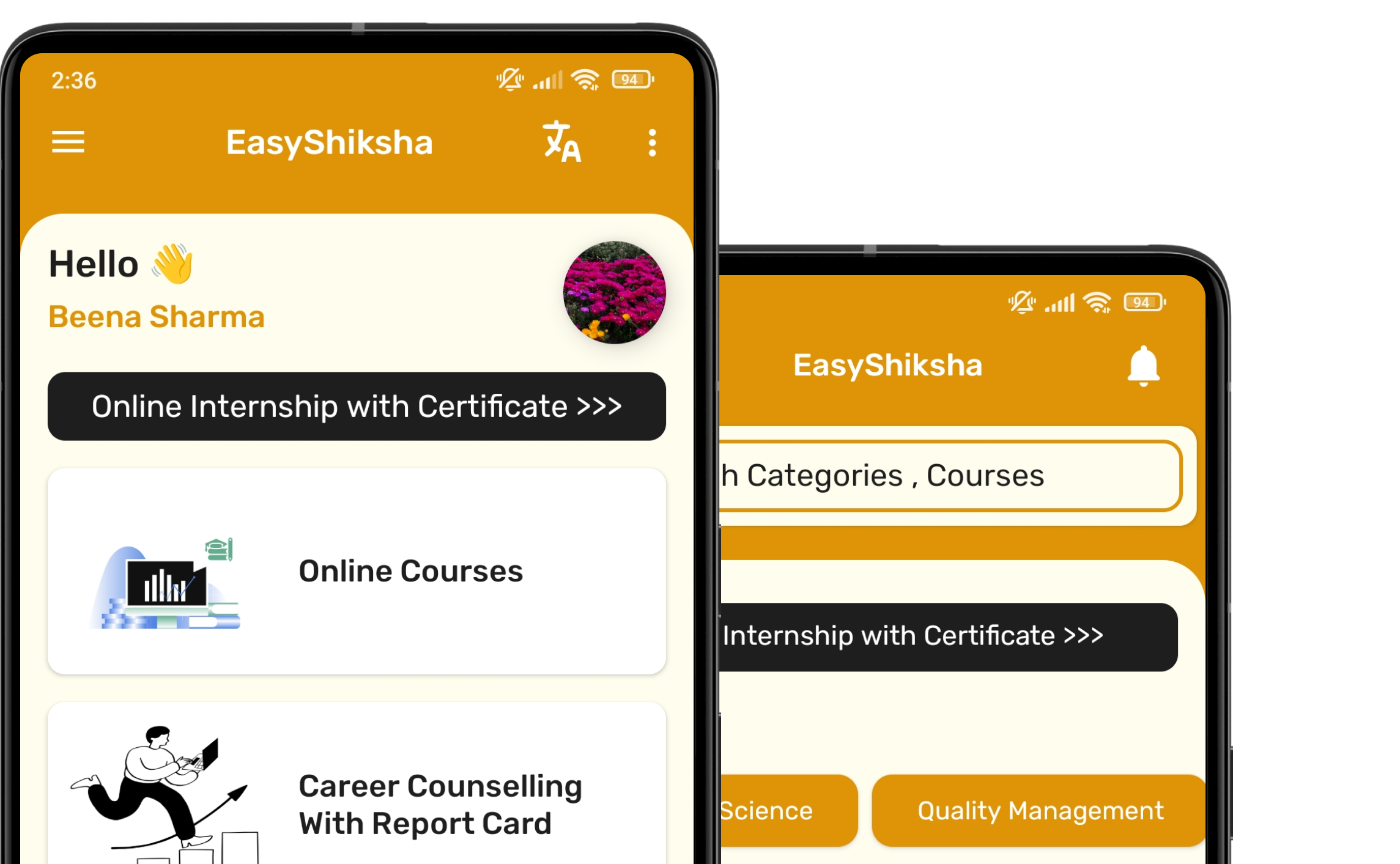


1 million+ learned on the EasyShiksha App
Trusted by Standards & Global Compliance Frameworks





Built under internationally recognized standards for quality, information security, educational excellence and business continuity.
ISO 9001:2015 | ISO/IEC 27001:2022 | ISO 21001:2018 | ISO 22301:2019 | DPIIT Recognized Startup | MSME Registered